Case Study II
DERBYSHIRE
Loss of a Bulk Carrier
Quick Link Index:
Vessel Particulars
Length: 281.94 Meters
Beam: 44.20 Meters
Depth: 24.90 Meters
Construction date: 1976
Location: United Kingdom
Classification: Lloyds Register
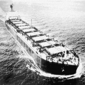
Vessel Type: Oil/Bulk/Ore (OBO) Carrier
Arrangement: Accommodations and machinery aft. Nine bulk cargo holds separated by double skinned bulkheads.
Arrangement and Construction Details:
Last of six sister ships designed in 1969 in the UK and built from 1970-76. The hull was double skinned and double bottom equipped. Each cargo hold was covered by 2 hatch covers (port and starboard). At the time of the loss, she had been in service only 4 years, and was considered a well-maintained ship, and was piloted by an experienced captain.
Back to Quick Link Index
Summary of Structural Failure
This paper discusses two possible explanations for the loss of the MV DERBYSHIRE during a severe storm, both of which postulate foundering due to structural failure of critical components. One scenario assumes the breakup of the ship due to fatigue failure of longitudinal structural members in the aft portion of the ship, while the other assumes foundering resulting from collapse of hold covers under sea loading. The two loss scenarios were compared in the light of the results of recent technical investigations and wreckage surveys. In the past decade this topic has produced intense debate in the maritime community, so the authors consider the topic worthy of review. The reader should bear in mind the complexity of ship systems and the highly irregular environment in which they operate, and realize that the loss of a ship is usually the result of many factors, including environmental, structural, and operational.
Back to Quick Link Index
Background
MV DERBYSHIRE was a British Oil/Bulk/Ore, (OBO), carrier transporting ore from Canada to Japan when she was lost during the typhoon ORCHID on the 9th or 10th of September 1980. She went down with all 44 on board without any distress signal. DERBYSHIRE is the largest British bulk carrier ever lost and has been the object of several investigations and discussions regarding bulk carrier safety. This loss is just one in a long list of bulk carrier losses from the 1970s to the mid-1980s. Every year 10 to 20 bulk carrier losses occur, where structural failure might be the cause, (Ref. 2). The shared opinion among marine engineers is that this is an unacceptable number of losses, and that it is necessary to improve the design criteria of the classification societies.
Because of the poor history of bulk carrier safety, a great deal of energy has been put into the investigation of the DERBYSHIRE casualty. It was hoped that if it could be recovered, the complete picture of the catastrophe would give valuable insight into potential structural weaknesses and inadequate ship design procedures.
History of Investigation
Since there initially was no evidence that structural failure caused the loss, the UK Government did not hold a formal investigation into the loss the DERBYSHIRE. In 1982, eighteen months after the loss, her sister ship, TYNE BRIDGE, experienced severe brittle fractures. These cracks initiated at frame 65 and propagated into the deck. After this fracture, the DERBYSHIRE Family Association (DFA) started investigating frame 65 cracks on the other sister ships. They hypothesized that this might be the cause of the loss the DERBYSHIRE. In 1986 another sister ship, KOWLOON BRIDGE, broke at frame 65 after grounding. These events caused a closer look into the loss of the DERBYSHIRE.
In 1994 the DFA had raised enough funds to conduct a survey of the wreckage. This first survey had the goal of locating the DERBYSHIRE and investigating the cause of the loss. The survey was completed in May 1994. The results of the survey were inconclusive, but they located an object assumed to be the stern, separated from the rest of the wreck by approximately 600 meters.
The survey led to further investigation. The new goal was to examine the loss of the DERBYSHIRE to learn more about structural weaknesses and to increase the safety of ships for the future . Thirteen loss scenarios were listed after an investigation of the service experience for the class and general casualty data for ships, specifically for bulk carriers, (Ref. 1). A lot of effort was put into the analysis of each loss scenario with the results that some were excluded while others were confirmed as more probable. This remainder of this paper discusses the two failure modes/loss scenarios that have been offered the most attention: Fatigue Failure at Frame 65 and Hatch Cover Collapse.
Back to Quick Link Index
Detailed Description of Structual Failure (Proposed)
Fatigue Failure at Frame 65
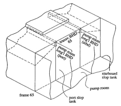
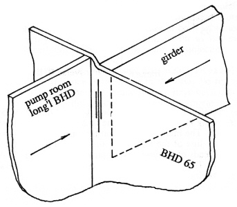
Before the possible structural defects are discussed, the general arrangement for the region around frame 65 must be described. Frame 65 is the transverse watertight bulkhead that separates Hold 9 from the pump room. The longitudinal structure makes a drastic change at Frame 65 from a main longitudinal girder to a longitudinal bulkhead separating the pump room from the slop tanks (see sketch of general arrangement below).
The possibility of failure at frame 65 was realized after the KOWLOON BRIDGE ran aground and broke into three pieces. One break occurred at the bow where it was resting on the reef and the second near frame 65. Other sister ships began reporting visible cracking in the deck above frame 65. These incidents caused the industry to examine the structural design for weaknesses. The examination revealed that the method used to transition from the longitudinal girder to the longitudinal bulkhead could have resulted in the catastrophic failure of the MV DERBYSHIRE.
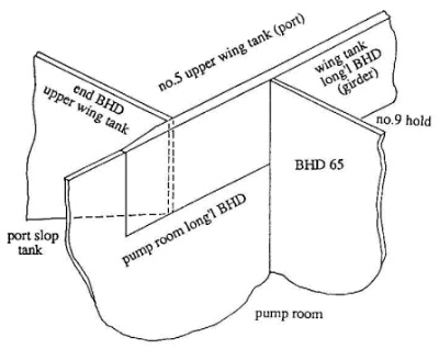
FURNESS BRIDGE, the first ship of the class, used an accepted design method for the longitudinal transition at frame 65 by continuing the girder through Bulkhead 65 and then tapering and finally welding it to the longitudinal bulkhead in the pump room (the drawing below shows the general structural design).
In the later ships, however, the design was changed to accommodate of coffer dams added to isolate the slop tanks from Hold 9 and the pump room. The new design ended the girder at Bulkhead 65 and started the longitudinal bulkhead on the aft side of the bulkhead (see drawing below for details).
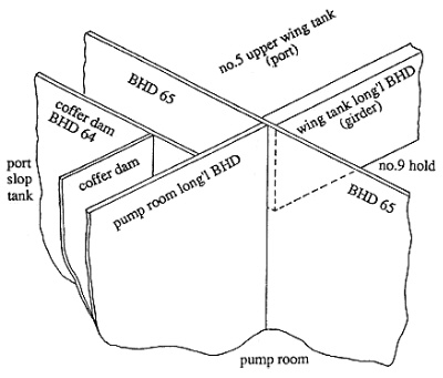
Ideally, the longitudinal girder and bulkhead would be in line at the transverse bulkhead, but if they are misaligned, the fatigue life of the structure could be reduced. As the ship cycles from hogging and sagging moments the misalignment causes the transverse bulkhead to be distorted fore and aft. The fluctuating distortions would result in high local stresses that could lead to cracking due to the shortening of fatigue life. The existing sister ships were found to have misalignments between the girder and bulkhead. Of course, the alignment for the DERBYSHIRE is unknown. Although the magnitude of the misalignment is under debate, it could have been as much as 45 mm (see drawing below for a basic representation).
Because of the high profile nature of the accident, eventually enough money was gathered to conduct a survey of the wreck. The survey revealed that the ship was in two main sections, but the stern section was only 600 meters from the forward section. Since the ship descended 4000 meters to reach the bottom, it seems unlikely that the break-up occurred at the surface. Therefore, failure in the region of Bulkhead 65 was not the likely cause of the foundering of the DERBYSHIRE.
Hatch Cover Collapse
The hatch cover design is another frequently discussed failure argument. In 1966 the International Convention of Load Lines, (ICLL), categorized a new freeboard class B-60, where the freeboard requirements of the ordinary B class may be reduced by 60 cm. The only requirement is that the ship survive flooding of one compartment without loss of sea keeping. The new B-60 class resulted in a decrease of freeboard in the majority of newly built bulk carriers. The smaller freeboard caused an increase of wetted deck occurrences and pressure head experienced by deck plating and hatch covers. The design pressure was set to 1.75 tonne/m2 at the same conference, but it can be questioned if this pressure is high enough.
Description of No 1 Hatch Covers
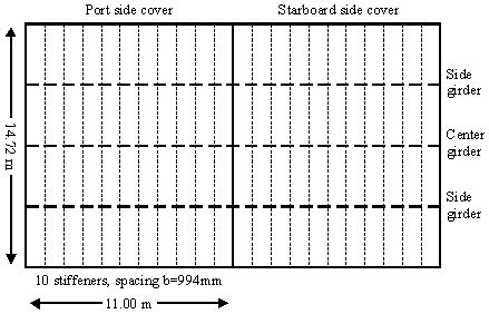
- There are two covers on each hatch with length 14.68 m and beam 11.0 m (Cover No. 1)
- The stiffeners are T beams with 635 mm web an flanges of 280 mm x 25 mm. They are tapered at the end with a depth of 483 mm.
- The transverse center girder is 920 mm deep with a small 75 mm x 25 mm flange and the side girders have webs of 560 mm and flanges of 100 mm x 25 mm.
- All webs and plate thicknesses are 10.5 mm.
The stresses in the hatch cover stiffeners met the requirements set by ICLL in 1966 according to Ref. 1. The requirements, taken from Ref. 3, page 3, are listed below:
- Hatch covers in the forward quarter-length (0.25L) to be designed for a uniform pressure of 1.75 tonne/m2.
- Level of stress not to exceed Ultimate Tensile Strength (UTS)/4.25. (which equals 0.40sigmay for mild steel)
- Limiting plate thickness for mild steel is b/100 or 6 mm, where b is spacing between stiffeners.
To determine the maximum load a rule-designed hatch cover can carry, we set plastic collapse as the ultimate state. The T stiffener has a plastic shape factor, s, of 1.25. (The shape factor refers to how much the load can be exceeded from first yield to full yield of the cross section). Then the ratio of the full plastic collapse load and the design load is:
[EQUATION: Ultimate stress / Design stress = 1.25sigmay/0.40sigmay = 1.25/0.40 = 3.125]
This means that we can increase the design pressure to a pressure of 3.125 (1.75 tonne/m2) = 5.47 tonne/m2 uniform pressure. This equals a water height of = 5.32 m over the hatch cover (Head = pressure/sea water density = 5.47 tonne/m2 / 1.028 tonne/m3). The collapse head shows the true pressure a rule-designed cover can carry before collapse. But did the cover truly fulfill the requirements? Finite element analysis of the hatch cover design shows that they would collapse under a static pressure of about 4.1 m (Ref. 1, pg 9) (hyperlink). This is above the ICLL requirement to resist a uniform pressure of 1.75 tonne/m2, but is still under the predicted collapse head of 5.3 m corresponding to the design pressure.
Basic Calculation Procedure for a Stiffened Plate Field
The stiffened plate of the hatch cover is modeled as a rigidly supported beam under uniformly distributed load. The beam length is taken as the stiffener span between the girders. The end moments, M, for a rigidly supported beam are given by:
[MOMENT EQUATION: M = pbL2/12]
where:
p = pressure = 1.75 tonne/m2 = 17.17 kN/m2
b = stiffener spacing = 0.994 m
L = span of the member = 14.72 m/4 = 3.68 m.
The longitudinals are assumed to be rigidly supported, because of symmetric loading on each side of the girder, and because the girder is usually much stiffer than the longitudinals.
The design moment for the stiffeners with length 3.68 m is then M = 1.963 tonne-m = 19.56 kNm. This is the maximum load the member must carry according to the design pressure. This gives a section modulus, Z, for the stiffeners of:
[SECTION MODULUS EQUATION: Z = M/sigma]
where sigma is the acceptable stress level in the member. The stress was not to exceed UTS/4.25, which equals 0.40sigmay for mild steel, where sigmay is yield stress (This is commented as an irrationally low stress limit, but it still exists, 1998).
Required section modulus is thus 19.56 kNm / [0.40(235 MPa)] = 204 cm3. The actual section modulus of the T beam stiffener can be calculated or taken from a table (Z = Iz /ymax where Iz is the 2nd moment of inertia about the z-axis and ymax is the distance from the neutral axis to the furthest flange). We do not use the dimensions of the tapered end of the stiffener because the ends are approximated as simply supported because the loading is not symmetric, and because the side plate at the end of the hatch cover is flexible. The most critical part of the stiffener is the end condition at the girder, so stiffener height at this location must be used in the calculations. The stiffeners used fulfill the requirements, according to Ref. 1. See also calculations in the
Appendix (MS Excel Spreadsheet).
These calculations
show that the required Z is about 204 cm3 (without corrosion allowance) and the actual Z is 1169 cm3, so the stiffeners seem to be over designed, if calculated in this manner.
It can be questioned whether these calculations describe the structure's capacity correctly, since the transverse girders are not as effective as assumed. One reason is that the depth of the side girders are smaller than the depth of the stiffeners, so in fact, the actual moment capacity of the girders is about 0.2MP, where MP is the plastic moment capacity of the stiffeners. The narrow flange of the girders provides much less bending strength than necessary to restrain bending of the cover. This leads to significant bending of both the girders and the longitudinals, and therefore, compression at the top of the members and the thin welded cover plating. The compression in this welded zone is substantial as bending increases toward collapse.
This is not mentioned in the references, but as far as we can calculate, the side girders do not fulfill the section modulus requirements. According to Det Norske Veritas (DnV) rules (Part 3, Ch.1 Sec.8, D201) the section modulus of the girders should be Z = 8133 cm3 (without corrosion allowance), but our calculations show Z = 2330 cm3 for the side girders, and Z = 4251 cm3 for the center girder. This is dramatically lower than the required scantlings
(see Appendix [MS Excel
Spreadsheet]). The requirements are
based on the moment equation above, but with 10 in the denominator because the girders can not be considered to be rigidly supported, but rather a condition between simple and rigid support which yields a maximum moment greater than pbL2/12 but less than pbL2/8.
Improved Design of No 1 Hatch Covers?
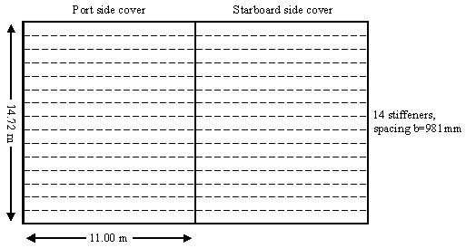
Faulkner (Ref. 1) suggests an improved design of the hatch covers where the three girders are removed, and the l0 longitudinal stiffeners are replaced with 14 similarly sized transverse stiffeners. He claims that this will improve the capacity of the cover by 85%, by decreasing the effective span of the stiffeners to 11.00 meters. This structure is lighter and also less expensive to construct. He claims the new structure is able to resist a pressure head of 7.0 meters, which is significantly better than the original design pressure head of 5.31 meters.
Faulkner has not shown his calculations and we are not convinced that this is a much better design. He believed that the girders are ineffective, because they will reach plastic collapse early. After the girder collapses the stiffeners have to carry all additional load, and now with a span of 14.72 m. In this aspect, the girders are ineffective and can be removed. By orienting the stiffeners transversely, the span is reduced to 11.0 meters.
Our calculations show that the new suggested design fulfills the
requirements for section modulus
(see Appendix [MS Excel
Spreadsheet]), but we
question the ability of the design to resist longitudinal bending.
Faulkner's design has no longitudinal stiffeners to prevent failure
in this mode, except the side plates of the cover.
Therefore we doubt the soundness of this suggested design.
Also, the stiffener ends are not rigidly supported so the
denominator in the moment equation should be closer to 8 than to 12,
and the maximum moment occurs at the midpoint of the stiffeners.
We calculated the maximum moment using 10, for the same reason as
for the transverse girders in the original design.
In our opinion it is better to increase the scantlings of
transverse girders in the original design and decrease those
of the stiffeners. The flange of the girders should be increased and
the depth should be equal for all three girders. A
possible solution incorporates three girders of 900 mm depth and a 300
mm flange, and stiffeners of 200 mm depth and 75 mm flange
(see Appendix [MS Excel
Spreadsheet]) . Note,
however, the design of the hatch cover is not a straightforward process, and more complex methods must be used to calculate the interaction between the deflection of the girders and the stiffeners.
Dynamic Loading
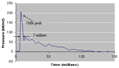
The hatch covers can fail not only due to static pressure, but under dynamic loading as well. Breaking or plunging waves impacting the covers can generate very steep pressure impulses. Even for mild steel this can lead to brittle fractures. The steep impulse is called the gifle peak, and evidence of this type of fracture has been found in DERBYSHIRE's wreckage. The peak is a result of the velocity of the water particles the moment they hit the structure. The retardation is extremely large because the fluid particles can attain very high velocities. To determine the velocities, we can use breaking wave theory. The classification society rules do not seem to account for the dynamic impact. The only requirements from DnV on design pressure for hatch covers is the static design head rhoH = 1.75 tonne/m2. (DnV Part 3, Chap 1, Sec 4, C401, 1998). This equals a pressure of 1.75 x 10³ kg/m2 (9.81 kg/N) = 17.2 kN/m2, and this is significantly lower than the peak of 200 kN/m2 shown on the graph. The dynamic loading has less inertia forces than the static pressure, because the amount of water involved is less. Therefore, the nature of the inertial forces effects the material surface. In contrast, the static forces have to be resisted by structural support and moment carrying members. Design for impulse gifle peaks from dynamic forces then becomes a question of material quality and ductility. So, it would be better to use more ductile materials in hatch cover construction.
 Water Impact Diagram
Extreme Wave Probabilities
One of the important topics that has been discussed during the investigation on the loss of the DERBYSHIRE, is the maximum wave height encountered during Typhoon Orchid. The goal was to establish a probable pressure head on the hatch covers. Some assumptions are required to model the behavior of the ship in typhoon driven seas.
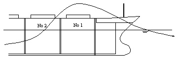
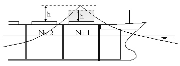
One assumption is that the ship is plunging through the steep crests rather than rising on the top of them. This is because these ships are long and heavy and have a natural pitch period longer than the wave period. We obtain a quasi-static wave profile when the wave is passing over the first hatch cover. This profile can be characterized with the equation:
[EQUATION h = alpha H - (F + C)]
where:
h = maximum head pressure over the cover
alpha = nonlinear wave ratio between the crest and the trough = 0.65 for a nonlinear wave in deep water
H = the wave height
F = freeboard = 6.9 m
C = coaming height = 2.0 m
From this profile we find the maximum mean pressure head hb at Hatch Cover 1.
[EQUATION: hb = h(1 B mL/4h)]
where:
L = length of the cover = 14.72 m
m = mean slope of the crest face and back, assumed to be 0.5 during Orchid.
The model of the nonlinear wave can be sketched as in the figure below.
From this wave crest model and extreme wave probability analysis, based on an energy spectrum that can be assumed realistic during typhoon Orchid, certain wave heights and probability of exceedence can be obtained, depending on the duration of the storm. The results of the analysis are shown in the table (Ref. 1, pg 9):
The results should startle most mariners, since the design head is about 1.7 meter head pressure (1.75tonne/m2 / 1.028tonne/m3) according to the rules, and total collapse occurs at 5.3 m head for a well designed cover. As a reaction there have been suggestions to improve class requirements. One is based on the existing stress criterion of UTS/4.25 and turns out to demand a pressure head of 4.5 m for No 1 cover, 4.0 m for No 2 cover, and 3.5 m for No. 3 cover (Ref. 3). Another suggests using the ultimate collapse of the covers and a factor of safety of 1.5. This turns out a design head of 9 m for No1 cover, 7.5 m for No 2 cover, and 6.0 m for No 3 cover (Ref. 1, pg 11). Including the safety factor gives a probability of collapse during a typhoon like Orchid of less than 1 % in 12 hours storm duration. As far as we know, the new suggestions have not yet been included in the classification society rules (DnV 1998, ABS 1995), but Faulkner comments that changes are discussed, and at least one classification society is about to change its design rules.
Implosion and Explosion
Large pressure differences develop when an air filled watertight body sinks. This knowledge can be used when inspecting a shipwreck. Any air filled compartment that was not damaged before sinking occurred would experience an increasing pressure differential with increasing water depth. At some point the outside pressure will exceed the pressure that the hull can resist. The compartment would then implode. When the compressed air is released from the compartment, there is a kind of explosion that result in shock waves in the water and the structure. This can lead to considerable damage, which can be confirmed by inspection. The DERBYSHIRE had many void spaces, and the cargo holds were also partly filled with air. So it should be possible to determine which compartments were damaged before sinking. From the design of each compartment, one can determine at what water depth the compartment should collapse, this would be the implosion pressure head. These vary a lot for each compartment. The hatch covers would collapse at about 4.1 meters submergence, but the hopper tanks would be able to resist the external pressure to a depth of 60 meters.
Final Survey
The final survey was conducted in two parts: Phase 1 in July 1996 and Phase 2 in March and April 1997. Phase 1 was a limited reconnaissance survey of opportunity, and undertaken by the same company that did the survey in 1994. The main goals were to confirm the stern location and visually inspect the stern and bow. The contractor for the second part was the Deep Submerged Laboratory of the Woods Hole Oceanographic Institution. They had great experience with surveys of the Titanic and Bismark. The goal was to either prove or disprove each of the 13 loss scenarios mentioned earlier. They hoped to confirm the cause of the loss, but if they were unsuccessful, the survey should demonstrate that nothing more could be done to determine the failure mode.
Back to Quick Link Index
End Result
The surveys confirmed that the object located 600 meters from the bow was the stern. It was considerably damaged by implosion-explosion forces. Bulkhead 65 was no longer connected to the stern. From these observations, the most probable conclusion to the Frame 65 argument is that the stern was intact when sinking started. The increasing pressure led to implosion of the stern as the ship sank deeper, with the hull eventually breaking near frame 65, which certainly was a weak point. As the stern and the rest of the ship continued to sink, the two parts separated, eventually settling only 600 meters apart. The final conclusion is that the frame 65 cracking was not the cause of the loss, but that this failure occurred as the ship approached the seabed.
The inspection of the hatch covers showed that all of them had external pressure as the initial failure mode. Most of the cracks occurred near the welding of the center girder, and at the connection of the stiffeners to the girders. The surveyors examined the edges of the tears, and from these observations they concluded (Ref. 1, pg 21) that several of the covers had collapsed before sinking started. They found indications of tearing damage between the longitudinals in 7 or 8 of the covers. This was probably from plunging sea waves encountered after the initial damage (Ref. 1, pg 9). The discovery of these failure modes confirms, or at least increases the likelihood, that the sinking was caused by hatch cover collapse.
Hopefully the incredible amount of money and effort invested during the investigation of the DERBYSHIRE casualty will lead the classification societies to develop design codes that can reduce the probability of similar failures.
Back to Quick Link Index
Acknowledgements
References:
[1] An analytical Assessment of the Sinking of the MV DERBYSHIRE, Professor D. Faulkner 1999
[2] A theory on the loss of the MV DERBYSHIRE; by R.E.D. Bishop, W.G. Price and P.Temarel 1990
[3] Design for Abnormal ocean waves; Professor D. Faulkner and R.A. Williams 1996. RINA
[4] Hull Structural design, Ships with length 100 metres and above; Det norske Veritas rules 1998, Part 3 Chapter 1
[5] Hull construction and Equipment; American Bureau of Shipping rules 1995, Part 3
Author(s):
Daniel Tarman and Edgar Heitmann
For questions and comments, Email:
Edgar Heitmann
Back to Quick Link Index
Back To SSC
Structural Failure Home Page
This web site was developed by:
JMS Naval Architects & Salvage Engineers
| 
 Last Updated: Mon Dec 19 2016